|
|
|
|
|
|
|
Product Details:
Payment & Shipping Terms:
|
| Usage: | Rotating Torque Measurement | Type: | Shaft Rotary Torque Sensor |
|---|---|---|---|
| Output: | Analog Sensor | Torque Direction: | Clockwise&Counterclockwise |
| Connection: | Couplings |
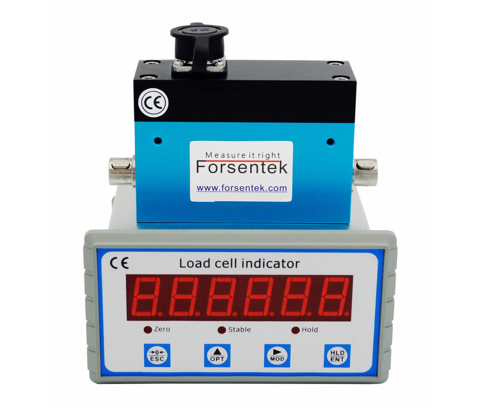
Rotary Torque Meter 0-5Nm Dynamic Torque Sensor With Digital Readout
Shaft to Shaft Dynamic Torque Meter FY02 is a slip-ring type torque transducer intended for rotating torque measurement in both clockwise and anticlockwise direction,slip rings are used to conduct the millivolt signal from the wheatstone bridge bonded on the sensing shaft which rotates together with motor shaft and gets the torque measured with maximum 0.2% non-linearity of the full capacity. Dynamic torque meter FY02 offers 0.1NM / 0.2NM / 0.5NM / 1NM / 2NM / 3NM / 5NM seven rated capacities to choose from. Keyed shafts located on both ends of the sensor can be connected to motor shaft and load shaft through couplings. Rotating speed of model FY02 goes up to 4000RPM, signal conditioner and display unit is also available at Forsentek. Typical applications for this type of torque cell are for example servo motor torque measurement, torque control for blenders, test bench applications, screw driver calibration, actuator test,etc..
![]()
Dimensions
![]()
Specifications
| Capacity |
0.1N-m / 0.88 lbf-in 0.2N*m / 1.77 lbf-in 0.5N-m / 4.4 lbf*in 1N*m / 8.8 lb-in 2N-m / 17.7 lbf*in 3N*m / 26.5 lbf-in 5N-m / 44 lbf-in |
| Rated output | 1.0 mV/V |
| Excitation | 3-15V |
| Zero balance | ±0.05mV/V |
| Nonlinearity | ±0.2% R.O. |
| Hysteresis | ±0.2% R.O. |
| Nonrepeatability | ±0.1% R.O. |
| Creep(10min) | ±0.1% R.O. |
| Safe overload | 150% F.S. |
| Ultimate overload | 200% F.S. |
| Compensated temp. | -10...+40oC |
| Operating temp. | -20...+60oC |
| Temp. shift zero | ±0.02% R.O./oC |
| Temp. shift span | ±0.02% R.O./oC |
| Input resistance | 350±30 ohms |
| Output resistance | 350±10 ohms |
| Insulation resistance | >5000M ohms |
| Ingress protection | IP40 |
| Material of element | Stainless steel |
| Cable | Ø5*3000mm 4-core shielded cable |
| Wiring code |
Red--Excitation+ Black--Excitation- |
A torque sensor is a transducer that converts mechanical torque into mV signal proportional to the applied torque.The acting torsion causes deformation of the measuring element,the bonded strain gage deforms accordingly which will cause the resistance change of the wheatstone bridge,under constant power supply, the output signal between Sig+ and Sig- will change proportionally,thus the moment can be measured by measuring the output signal from the transducer.
Torque sensor output: = (Power supply * Rated output) * Load / Capacity
Rated output is normally within 1mV/V~3mV/V.
Power supply is normally within 3-15V.
Load / Capacity is within 0-1.
So the torque sensor output signal is normally within 0-45mV(-45mV...+45mV for bidirectional load cell).
Example one: FY02-1NM with 1.0mV/V rated output powered by 10V DC,the output range is -10mV...+10mV.
Example two: FY02-2NM with 1.0mV/V rated output powered by 3.3V DC,the output range is -3.3mV...+3.3mV.
Torque sensor + Signal amplifier to deliver -5-5V 0-10V 4-20mA output.
Example: FY02-5NM working with -5-5V amplifier,the torque-output relationship will be 0-5Nm torque in CW direction VS 0-5V output,0-5Nm torque in CCW direction VS 0-(-5V) output,which is linear within the error range.
Torque sensor + Digital indicator:
-Display torque value in real time
-Peak holding to grab the maximum force during testing
-RS485 or RS232 interface
-0-5V/0-10V/4-20mA analog output
-Switch output
![]()
Contact Person: Mr. Tarik Lu
Tel: +86 755 84536383